This tutorial is assuming that you already own a Raspiboy. Whether you already bought one and have yet to assemble it or maybe you purchased one after reading my review of it. If you haven’t read my review of it yet, I have the link for you right here. This tutorial tells you everything in terms of assembling the hardware. If you need to know how to make a Raspberry Pi run Retropie, the internet can help you with that, it’s well documented.

Making Certain You Have Everything
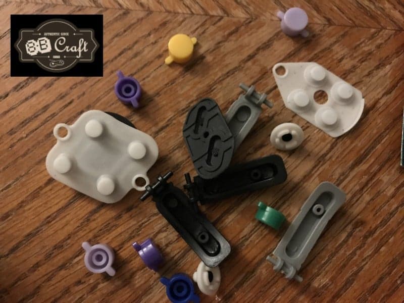
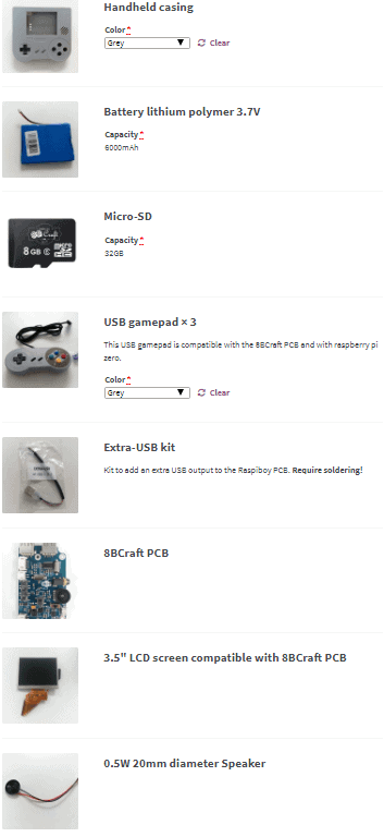
It’s always a good idea to make certain that the seller has packed in all of the parts that you are supposed to receive. That keeps you from going crazy and thinking you lost something further down the road. There’s not much else to add to this other than the fact that this is a good practice before ever assembling anything that contains a lot of parts. Just below this paragraph is a picture of all of the items that you should have in your box from 8B Craft. Not depicted below is also the small zip lock bag of screws and controller buttons.
What Hardware You Need
Aside from having almost everything that you need already in the kit, there are some other essentials that you’re going to need here. The first of which being a smaller Phillips screwdriver. I’m not certain of the exact size, but as long as it’s smaller than your standard household screwdriver, you’re good to go.
The biggest piece of the pie here, is, well, the Raspberry Pi. The kits, unfortunately, do not have a Raspberry Pi in them. I do wish that there was a slightly pricier version of the kit with a Raspberry Pi in it, but alas, there is not. So what does this mean for you, the end user? If you’re purchasing this kit online, I would highly recommend that you buy your Raspberry Pi right after ordering your Raspiboy. The Raspiboy is likely to arrive much later than the Raspberry Pi, so this means you’ll already have your Pi when the kit arrives. The specific model of Raspberry Pi that you need is the Raspberry Pi Zero. It is the only one that will fit into this device. Nothing else. It doesn’t seem to matter which revision you get of the Raspberry Pi Zero, but obviously the more recent the revision, the better the emulator performance you’ll get.
If you’re sitting there thinking that you already have the Raspiboy and you were coming into this tutorial thinking that that’s all you needed and do not have a Raspberry Pi Zero yet, I’ll have a link at the bottom of this page for you to purchase one. I would still read all of this tutorial though, even if you’re missing the Pi, as it’s useful to know it all through first. Then when you actually go to assemble it, you can glaze over this again and have a sense that you feel like you know what you’re doing.
Additionally, you may need one last thing. If you do not have a way to read SD cards on your computer, you will need one. The microSD card comes with an SD card adapter, but if you do not have an SD card slot on your computer, you will need to get a USB card reader for your computer. Other than that though, you should be good. If you have your small Phillips screwdriver, Raspberry Pi Zero, and all of your kit’s pieces are present? Then you can safely move onto the next section.
What Software You Need
All of the software I’m about to talk about will be explained in the instructions at the bottom. For now, I’m just letting you know what to download before we get into the instructions. To start things off, you will need the most up to date version of the emulator software for the Raspberry Pi Zero. The emulator we’ll be using is an all in one solution called Retropie. You can download the newest version of that here.
You will then need to download Win32DiskImager. I would host a link to it, but since it’s possible that a newer, better version could come available, I will just suggest to you that you simply Google it. It is completely free and is for Windows. There is an alternative software for Mac called Etcher. I will not be able to tell you how to use the Mac version as I no longer have a Mac, but I would assume that the steps will be very similar in nature.
The last thing that you’ll need to download is less software and just more something that you need to have handy for some future step. You need to download the config.txt file from here (right click “save target under…”) to help fix some pieces of Retropie so that it will be more compatible with the Raspiboy.
Those three downloads are the only parts that you will need for getting Retropie up and running on your soon to be assembled Raspiboy. You can now head onto the full instructions below.

STEP ONE: Software Instructions
- Extract the Retropie archive. You will see the .img file inside.
- Plug the microSD that came in your Raspiboy kit (or a different microSD card, if you’d like) into your computer.
- Install Win32DiskImager and then start the program.
- Now, select the letter of the microSD drive, make certain you are not choosing your other primary harddrives or other devices.
- In the next field, browse to find the .img file that you extracted from Retropie.
- You can now burn the image to the drive. It shouldn’t take but 3-5 minutes on average. Depends on your PC’s CPU I suppose.
- Now, close the program and open the microSD folder on your computer. On the root you should have a config.txt file, delete it.
- Now, place the config.txt file that you downloaded earlier on the root.
- Once that’s done, you can now take the microSD card out of the PC and insert it into the microSD card slot on the Raspberry Pi Zero.
STEP TWO: Hardware Instructions
- Grab the front faceplate of the Raspiboy and place it face down on a static free surface.
- Place your Raspberry Pi Zero face down onto the four posts to the right of the screen’s opening. It will align perfectly.
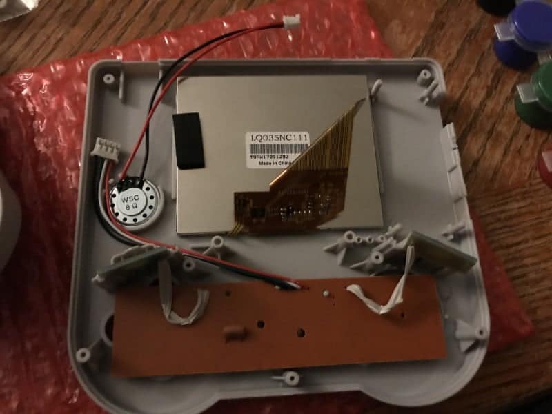
- Being careful not to break any pre-existing soldered cords, place the screen and speaker in their dedicated grooves (depicted in Picture One).
- Again, being careful with soldered cords, place the small rectangular shoulder buttons boards into place (depicted in Picture One).
- The screen will use the ribbon cable and plug into a port on the bottom side of the 8B Craft PCB. Do this by sliding back the small clip. Then the ribbon cable end will fit into it. You now need to slide the clip back down into place to lock in the ribbon cable.
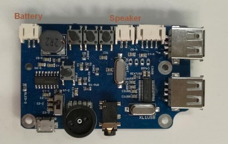
- Now, insert the 8B Craft PCB on top of the Raspberry Pi Zero on the four posts. There are little points all over the board, they will face down into the Raspberry Pi. If they face up and none of your ports match up, then your PCB is upside down. Simply take it off and flip it right side up.
- Now you can place the battery on the back left side of the screen. Then plug it and your speaker into the PCB. Make 100% certain they do not get in the wrong ports. From left to right it is the battery and then the speaker. (depicted in Picture Three).
- You now need to set the buttons in place on the back of the controller PCB. If you have no prior knowledge of disassembling and reassembling a retro controller, this part may be harder for you. You may have to watch a video as it is hard to explain (I’ll do my best). If you’ve messed with retro controllers, it’s a cake walk.
- First choose the button colors you want from the 2 color sets. Grab the rubber start and select buttons and place them in first. Then place in your A, B, X, Y buttons. The concave ones go in the top two slots. Then you can drop your D-Pad into position as well.
- Now that the physical buttons are in place, you need to place in the button contacts. First, grab the large white rubber contact with one hole on the outside edge. This is for your D-Pad and will sit right on top of it and the hole goes onto it’s one small post. With the other large rubber piece that has two holes, that will sit behind the A, B, X, and Y buttons. Align the two holes with the two posts.
- The last pieces are the shoulder buttons. On the back panel of the whole device, place your L and R buttons respectively. They have one post that goes into one hole, this is so that they can swing up and down.
- On the main faceplate, above the shoulder PCB’s you should have a small slot. This is for the last 2 remaining rubber pieces. They sort of look like thumbtacks in shape. These go pointy side up and just kind of sit there. They will be secured in place when the two shell halves come together.
- Now take the controller PCB and face it down (depicted in Picture One).
- Plug the end of this cord into the 8B Craft PCB in the only remaining port. It will fit perfectly.
- Now you have to do the all too frustrating task of aligning the backside and front side of the shell together. I cannot really help too much with this part. Sometimes you may need to adjust the battery or cords. Sometimes the trigger buttons are dumb. You will eventually get it.
- While holding it tightly closed with one hand, drop your screws into the holes and then tighten them one by one.
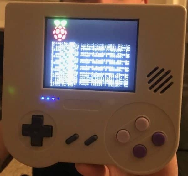
- Now, using the power button on the back, you should be able to boot into Retropie! It will prompt you with assigning buttons and what not. Have fun!
Final Notes
It is so well documented already on how to add ROMS to your Retropie. This device has two full fledged USB ports, so you can use the tutorial here and load up ROMS! If you have an issue with the font size in Retropie you can do something about that by clicking here. If you have a white noise issue, do the following. While Retropie, press start, select audio settings, increase to 100% then you can reduce the volume wheel, thus reducing the overall white noise. If you still want a full fledged video, here is the official one for you. If you’d like to know how to add the third USB port, here is the official video from that.
To turn ON the Raspiboy use the switch on the back. To turn OFF the Raspiboy, first shutdown from within the software, then when LCD goes crazy, use the switch on the back. If you have a 1.1 Raspiboy, it should not be used while charging. You’ll know you have it because it will power off if you try to use it while it’s charging. Also when plugging/unplugging power cable into a turned ON Raspiboy it might crash the unit. So only do this when the unit is off. To switch to HDMI you need to turn OFF the Raspiboy, plug the HDMI cable, turn ON the unit. Same if you want to switch back to composite. The micro-USB connector is for CHARGING ONLY. You should not try to connect a device there or try to connect SSH through that connector it will fry the PCB!
If you’re interested in buying a Raspiboy kit, click here.
If you already have the kit and need a Raspberry Pi Zero, click here.
Stay tuned here on Hackinformer.com for more reviews and follow us on Twitter @Hackinformer
If you like the author’s work, follow him on Twitter @V1RACY and remember to retweet any articles of his that you see!