Recently we typed up an article covering everything you might need to know about the Game Boy backlight kit from Handheld Legend. If you didn’t catch that, it was great fun, you can click here to read it. So now what? You’ve already ordered the kit and you need instructions. Or maybe you’re still on the fence because you’re afraid that it might be too complicated (there are purchase links at the end if you decide you want one). Let me help with those as we’re going to cover the ins and outs of how to install the kit right now!

What You Need First:
- Handheld Legend’s IPS v2 Kit (link at the bottom if you need one still).
- Phillips head screwdriver.
- Triwing head screwdriver.
- Flush cutters (or diagonal blade pliers, or Dremel tool, or an Exacto knife).
- Tweezers.
- Soldering iron (if you want sound).
Video Tutorial (for those of you who don’t want to read):
Text Tutorial (for those who don’t want to watch an 19 minute video):
Part 1: Game Boy Disassembly
- Turn your Gameboy upside down so that the screen is facing down on the table.
- Take your battery door off and remove any batteries. Set all of that aside.
- Using the triwing head screwdriver, take the two screws out of the battery compartment.
- Now, remove the other four screws you see along the back. Once you’re done, you’ll no longer need the triwing driver.
- Once all of them are removed, the backplate should come up. The two halves are still connected via a ribbon cable.
- Unplug this ribbon cable from both ends. It’s simply wedged in on both sides, so just pull it out with gentle force.
- Set the backplate (the one with the battery compartment) off to the side for now.
- You now need your Phillips head screwdriver. There are ten screws that are holding the PCB down. Take all of them out and keep them close by.
- After doing this, the PCB should lift out. Mine was still wedged over the posts, so I recommend using a spudger or a credit card to get under one of the edges. Then use your finger to keep that side up and then use the spudger/credit card to lift another corner. That should lift it up with zero booboos.
- The screen is attached to this PCB. You ‘ll need to keep this handy for later.
- You’ll now see rubber membranes over the D-Pad and face buttons. The Start/Select button is also a membrane, remove it as well.
- Now you can take out the D-Pad and face buttons. I took this opportunity to clean all of the buttons and membranes since this DMG had never been opened and cleaned.
Part 2: Shell Modification
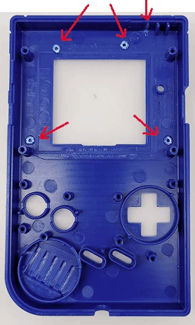
- For step 2 of this section, you’ll need to reference the picture just below.

Click to enlarge. - You need to get your cutting tool of choice (dremel, flush cutters, etc) to cut the posts in the picture. You do not need to take them all of the way down to ground zero. But you need to chop a bulk of it off. If it looks like there’s still some above the surface and your tool won’t let you get any closer, don’t fret. The screen will still fit as it should.
- This step is optional, but if you wanted to file them to remove any worry from your mind, you could do that now.
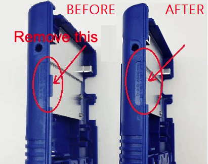
- There is one more thing that you have to trim off. Remember how I said to keep the back half close, well grab that now.
- For step six, you need to reference the picture below.
Click to enlarge. - Cut away this piece of plastic from the back half. It’s the last piece of cutting that you’ll have to do.
- At this juncture, you’re done with the back half. You can set it aside again. You’re also done with the cutting.
- Grab your front plate and set it lens side down again on your table, we’re ready for the next section.
Part 3: Display Assembly
- Now it’s time to remove the protective plastic from the display on your new screen. Make certain to no longer touch it or get the screen dirty.
- After that, plug in your screen to the small PCB that came with the kit. It was the hardest thing for me to do honestly because of the lock tab. Once it’s in and locked, you can move on.
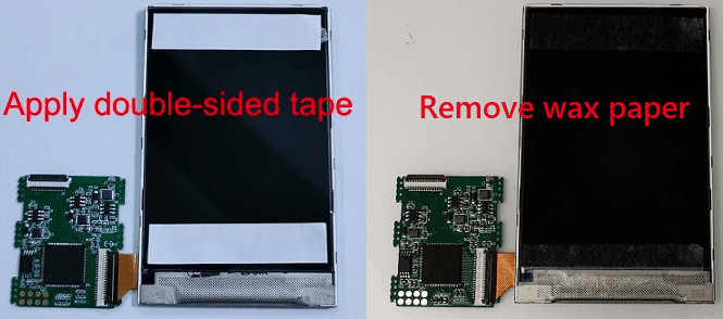
- The next step is the application of the double-sided tape that comes with your kit. You’ll need to reference the picture below to help.
Click to enlarge. - One strip goes along the very top and one strip goes along the very bottom of the display.
- Once you have the two pieces cut to length and applied, you now need to remove the wax paper. This was also pretty hard to do without pulling the tape back up. I recommend tweezers to get ahold of one of the paper corners and lift up.
- Now that you have a nice and sticky display, turn it upside down and hold the small PCB against the back of it. It doesn’t matter where, you’re doing this to keep it out of the way.
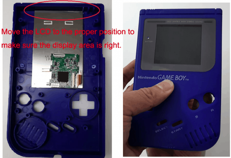
- Step 8 is very much for you to get right. I recommend reading all of step 8 before attempting it. Nevertheless, you’ll definitely want to use the picture below as a reference.
Click to enlarge - The idea here is to align the screen so that it is upon the area that you cut the skinny plastic tab off of enough to where it is centered from the front. Meaning, if you look at it from the front side, you won’t see the left or right white bezel of the display. The real trick here is to keep the tape from touching too much, otherwise, you’ll have to pry it back off of the shell (which is incredibly difficult). Just be gentle, take your time, and move it millimeters at a time until you find the sweet spot.
- Once you’ve found the sweet spot apply gentle pressure to get the tape to stick onto the shell.
- Now use some of the extra length of provided tape to tape the display down. You don’t need to remove the wax paper from the top as you only need it to be sticky on the bottom side of the tape.
- Now rest the Game Boy lens side down again. My kit already had the additional thin ribbon cable coming out of the top of the small PCB. If yours did, continue to step 1 of part 4 below. If not, find that compatible ribbon cable in your kit (skinny, white) and apply it to the ribbon cable lock at the top of the small PCB. Make sure you’ve oriented it correctly.
Part 4: Speaker Soldering
- Move your front shell out of the way so that you can solder.
- Turn on your soldering iron and let it warm up. For the following steps, you don’t need it terribly hot. You’ll be doing basic soldering.
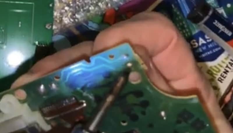
- First off, you need to desolder the two speaker wires from the old PCB board. To do this, simply heat up the solder point while gently tugging the cord from the other side of the board. When it’s warm enough, the cable will come free. Use the (fuzzy) picture below for reference if the explanation isn’t obvious enough. Just make sure you remember which cord was in which hole. Maybe mark one with a sharpie for the right hole and leave the cord for the left hole unmarked.
Click to enlarge. - Now, on the new PCB, you’ll find two holes in the exact same place they were on the old PCB. They’re very small holes, you can’t pre-tin your cords.
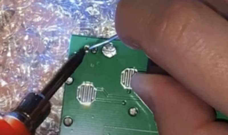
- Just push the correct cord into the correct hole and solder it in place. I just touched the solder to my soldering iron and let a single droplet hit each cord and that was sufficient. It created a solid hold and worked perfectly the first time that I tried the speaker. Feel free to use this (less fuzzy) picture for reference.
Click to enlarge. - Now feel free to do whatever you want with the old PCB/Screen combo. It’s not needed ever again, maybe save it just in case.
- Set the new PCB assembly aside again, you’ll be needing it soon enough.
Part 5: Game Boy Reassembly
- Bring your front shell piece back over to your table and face it lens down again.
- Drop the D-Pad and face buttons back into place in the shell.
- Now, remember those rubber membranes you removed (and hopefully cleaned)? It’s time to put them back in. You will notice that the membranes don’t just rest however you want them to, however. They have a very specific shape and will go exactly on posts/pegs to hold them in place. The Start/Select membranes are also shaped in such a way that they can only fit one direction.
- Make sure that the ribbon cable that is sticking out the top of the small PCB is still sitting there.
- Pick up your brand new PCB from the kit now and place it back on the posts the way the old one was before.
- You’ll see that the new PCB has a small notch cut out for it for the ribbon cable to fold over it. If it’s not aligned properly, then go back to the small PCB and move it left or right until the top ribbon cable sits in the slot made for it.
- Once that’s done, use a bit of the double-sided tape to keep the small PCB in place.
- Now you can officially set the large PCB in place on it’s posts.
- This is a great time to now place the ribbon cable at the top into it’s position on the large PCB and lock it in place.
- Now you’ll need to put your speaker back into place. There’s a small tap on the speaker that fits into a small opening on the left of the speaker hole. It’s hard to explain, but the speaker can only go in one way. It will fit just under the edge of the PCB. So lift up the PCB a little bit if you need to.
- Grabbing six of the old PCB screws, screw the new PCB into place. Use the picture below for reference.
Click to enlarge. - Now grab the last ribbon cable from the kit. This will replace the old one that connected the two Game Boy halves together. Again, there are no ribbon cable clips, you simply slide each end into the bracket designed for it.
- Grab your new side plastic pieces from the kit and put them into place. They make look uniform, but they actually fit on a specific side. You’ll feel them go into place if you have them on the correct side.
- Now for the easy part! Simply apply the backplate and screw in your four outer screws and two battery compartment screws using the original triwing screws.
- At this point, we’re almost done, but you should test to make sure you assembled it correctly. Pop in some batteries, pop the battery cover on, and turn power it on. Make sure you hear audio and see the Nintendo logo (or black rectangle if there’s no game in) come on screen. If this doesn’t work, disassemble everything and inspect your work. Once you’ve figured out what was missing, reassemble and power it on.
- All good? Enjoy your backlight nostalgia!

Purchase Link:
Click here to purchase the IPS v2 kit.
Click here to purchase the optional aligning bracket.
Stay tuned here on Hackinformer.com for more reviews and follow us on Twitter @Hackinformer
If you like the author’s work, follow him on Twitter @V1RACY and remember to retweet any articles of his that you see!