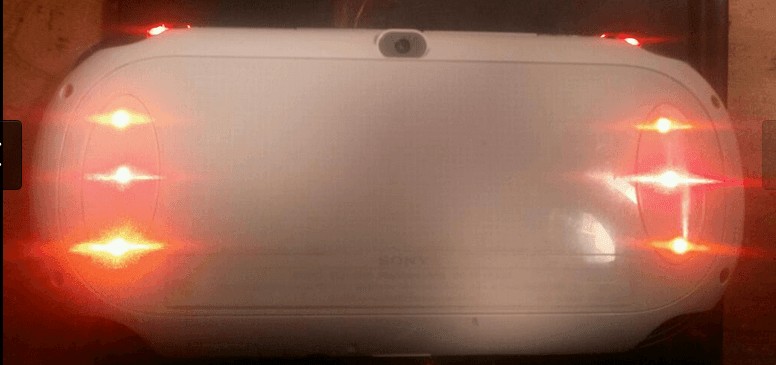
WARNING: ANY AND/OR ALL DAMAGE YOU DO TO YOUR SYSTEM IS YOUR RESPONSIBILITY NOT MINE!
This is one of the simplest mod to do, it takes a little bit of time and patience. I’ve also applied a new approach to soldering the wires to the psvita speakers which I will be discussing in the post below. The tools needed for this mod are:
-a soldering iron
-solder
-a multi meter
-1206 leds with a forward voltage of 1.8V-2.2V( i have chosen red and orange because they met these parameters,make sure to double check!)
-an electric drill
-a 3/32″ drill bit( this is used due to the size of the led and you want it to fit snug inside the whole)
-super glue
-30 gauge solid core wire
-Wire strippers: I purchased mine at my local radioshack
Before starting this, know exactly which configuration you are going to choose. I have done 4 configuration so take your pick. This will dictate how many holes you need to drill:

Config 3: If you’re going with this then there is no need to drill the center.
I was in the middle of the 4th config.
Step 1: Getting the back out-once you have disassembled your vita and disconnected the battery. The rear touch connections you should be meet with this(I have removed my battery for spare parts but this wont impact the installation)
Step 2:Drilling the Holes-Now here is where accuracy is key, get your drill bit connected to your drill. Then drill the hole(s) based on your desired configuration.
The third point can be a little tricky but not to worry. To get to the third point just lift off the psvita speakers.
Once you’ve drilled your hole(s), make sure to clean off any excess material thoroughly as this can impact how well your led will fit into the hole.
Step 3:Soldering the leds and wire stripping-Ok the hard part is over*wipes brow* now on to the good old leds. There are a few methods to soldering wires to leds. Now is the time for the wire strippers and 30 gauge wire. Cut off a fairly long piece of the 30 gauge wire and stick it in the hole you’ve just drilled, now bring the other end of that wire to the psvita speaker prong and wrap it around it. Now that you have the approximate length for your wire you can cut the excess wire from the speaker prong. I personally have a vice grip that I use to hold my wires in place, so I can get a good clean connection like so:
Always remember to do a stress test, nothing worse than going through all this heat to find out the connection just rips right out.
Step 4: Testing your connection-This is a must after you’ve soldered all your lights, take out your multimeter and check if the light is active like so:
Step 5:Fitting your leds-It is time to secure your leds into place. To do this, you’ll be needing your flat head and your superglue. What you wanna do here is make sure the leds, you fit are in a vertical position like so:
Reason for the vertical alignment is because you want the wire to rest right on top of the speaker prongs. Make sure not to use to much force on the led otherwise you will shatter them and rage shall consume you. Once you feel a small pop that means the led is secure. Remove the led so you can add the super glue in the holes. Now fit the leds vertically into place using the flat head again and wait a few minutes. Once you’ve seen that the led is being held in place well by the glue you can remove your flat head from the led.
Step 6: soldering your leds to the psvita speaker prongs-The technique I am going to use is to solder the wires underneath due to the volume of wires I have. If you solder to many wires to the top part of the speaker you will receive zero sound. In my case I had to solder them to the bottom side of the prong like so:
As you can see I slipped my wires UNDER the speaker prongs not over and soldered each side to make sure it wouldn’t move. I have a bunch of wires due to the fact that I have the speaker holes and triggers done as well. I suggest if you are doing 1-2 lights per side to solder on top. Anything more than that will just flex the wires underneath so that the prong is kept clean. Now you just have to assemble the unit and enjoy! Thanks for stopping by! Let me know if there are any alterations that can be made as this is my first tutorial well..EVER.
by: Bl4ckmonkey you can follow me on twitter @Bl4ckmonkey1


